A while ago, I obtained a nice, compact test equipment grade 30 watt linear power supply, an HP E3612A, from a local surplus reseller. It is of early 1990s vintage and has an attractive output range: 0-60 V at up to 0.5 A, and 0-120 V at up to 0.25 A. Both constant current and constant voltage settings are available. (One can directly drive a regenerative one-tube receiver with that upper voltage range!)

Being HP equipment, it of course will go beyond that range to 90 V on the 0.5 A setting, or even 135 V on the 0.25A current setting. A former HP employee told me the key to their success was attempting to build things that could outperform the published specifications by at least 3 dB and sometimes even 10 dB, ensuring they would minimize returns that way. It explains why vintage HP equipment has such a dedicated following and why items from the 'golden age' of HP survive decades in good working order. The manuals for these instruments are also unbelievably detailed with real schematics and calibration procedures! Very nice.
This instrument however was not feeling well when I obtained it. Voltage in either high or low range would not go very high even with the adjustment knob all the way to maximum, and current limiting was not working either. So I opened it up, and discovered of course the bane of repairing existence: a couple capacitors had failed and leaked all over the board, disabling the regulation circuits. Cleanup time!
Fortunately, no traces had been eaten through by the corrosive stuff, although some of the traces had their solder mask partially eaten away. Can you spot the bulging electrolytics C7 and C13?

The problems are evident here when examining C7 close up - check out those nearby traces:

Time to desolder, and while I was at it, time to also replace all the electrolytics (except the very largest ones, which seemed OK and which were also RTV'd down to the board). Removing the old ones revealed further electrolyte ugliness:

Here's the bottom of C7 after removal. No thanks - destined for the trash.

The bottom of C13 was no better on the board - nearly took out the rectifier CR9 next door.

With a lot of isopropyl alcohol, KimWipes, and Q Tips, I managed to scrub off the board and remove nearly all the nasty green remnants of the failed electrolytic caps. Removing the old electrolyte was definitely necessary, as measuring resistance between two parts of the board covered in solder mask would at times give < 1 megohm resistance where one would expect nearly infinite resistance. (Electrolyte goo is conductive!) Not a good thing for a power supply. Here's a typical Q Tip after one pass over the board - ugh:

Things look somewhat better after cleanup. Traces look damaged but they tested fine.


After my Digikey order came in, I set about replacing all the caps I had carefully removed. After a quick power check and calibration following the manual's procedure, this returned the E3612A to full service. Success!
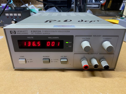
Here it is putting out over the rated voltage.
Here's constant current mode, using a ceramic 0.1 ohm 5W resistor as a load.

One down, many to go...
Addendum:
For those reading this with a similar supply that is not feeling well, I found some useful Youtube examples of how to get the case open and repair. These might be helpful.


